3 Projection of Planes
3.1 Introduction
A plane is a two-dimensional surface that has only length and breadth; its thickness is considered negligible.
In engineering graphics, planes are depicted using various geometric shapes, including:
- Squares
- Rectangles
- Circles
- Pentagons
- Hexagons
- Other polygons
These plane figures form the foundation for understanding and visualizing the projection of objects onto different reference planes.
3.2 Typical Problem Statements
- What is usually asked in problems?
- To draw the projections:
- Front View (F.V.)
- Top View (T.V.)
- Side View (S.V.)
- To draw the projections:
- What information will be given in the problem?
- The type/description of the plane figure (triangle, square, hexagon, etc.).
- Its position with respect to Horizontal Plane (H.P.) and Vertical Plane (V.P.).
- How will the position with H.P. & V.P. be described?
- The incination of the surface/ lamina of the plane with one of the reference planes is given.
- The position/inclination of one of its corners/edges with repect to the other reference plane.
- This means the plane, we consider, is usually inclined to both reference planes.
3.3 Stages for Drawing Projections When a Plane is Inclined
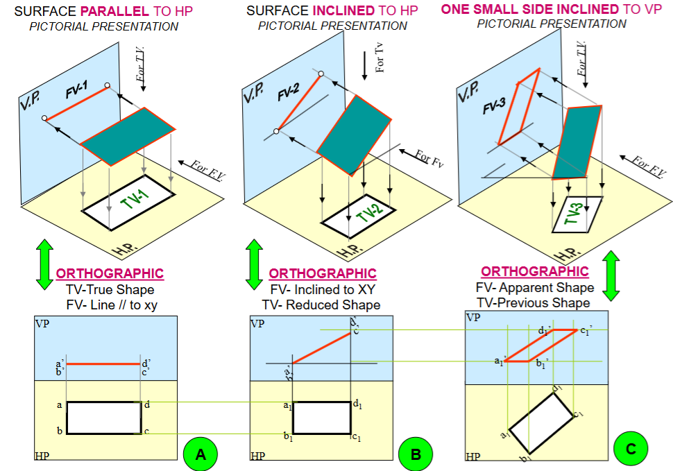
image reference
The process starts by assuming an initial simple position, then introducing the surface inclination, and finally introducing the side/edge inclination.
Initial Position: Surface Parallel to one Reference Plane
Assumption: The plane figure is initially assumed to be parallel to one of the reference planes (either HP or VP). This allows one of its views to show its true shape.
Views:
If the surface is assumed parallel to HP, the Top View (TV) will show the true shape of the plane figure. The Front View (FV) will appear as a line parallel to the XY line.
If the surface is assumed parallel to VP, the Front View (FV) will show the true shape of the plane figure. The Top View (TV) will appear as a line parallel to the XY line.
Surface Inclination
Description: The inclination of the plane’s surface (lamina) with one of the reference planes is introduced in this step.
Transformation: The view that was a line in the previous step (e.g., FV if the surface was parallel to HP) will now be drawn inclined to the XY line at the given angle. The other view (e.g., TV) will show a reduced shape.
Edge/Side Inclination with the Other Reference Plane
Description: The inclination of one of the plane’s edges (or a specific feature like a diameter or diagonal) with the other reference plane is introduced. This leads to a case where the object is inclined to both reference planes.
Transformation: The view from the previous step that showed the “reduced shape” (e.g., TV in Problem 1) is now redrawn such that the specified edge or feature makes the given angle with the XY line (representing the other reference plane). The final views will show apparent shapes.
Read the problem and answer the following questions:

1. Surface inclined to which plane? "H.P. or V.P."
2. Assumption for initial position? "Parallel to H.P or V.P."
3. So which view will show the true shape? ; "Top view or Front View"
4. How to draw the edge/ corner of the plane which rests on one of the planes?
   "If an edge of a plane rests on plane draw the view in step - 1, with the edge perpendicular to the XY line. Instead, if a corner of a plane rests on a plane, draw the view in such a way that the line joining the corner and the center of the plane is parallel to the XY line."